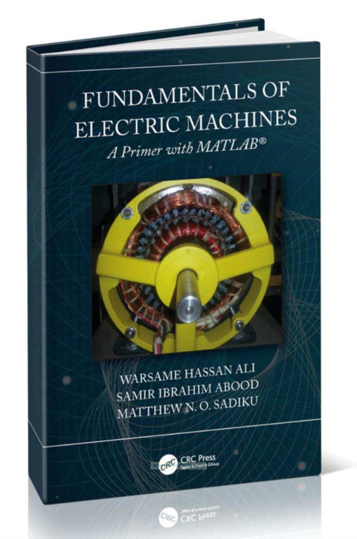
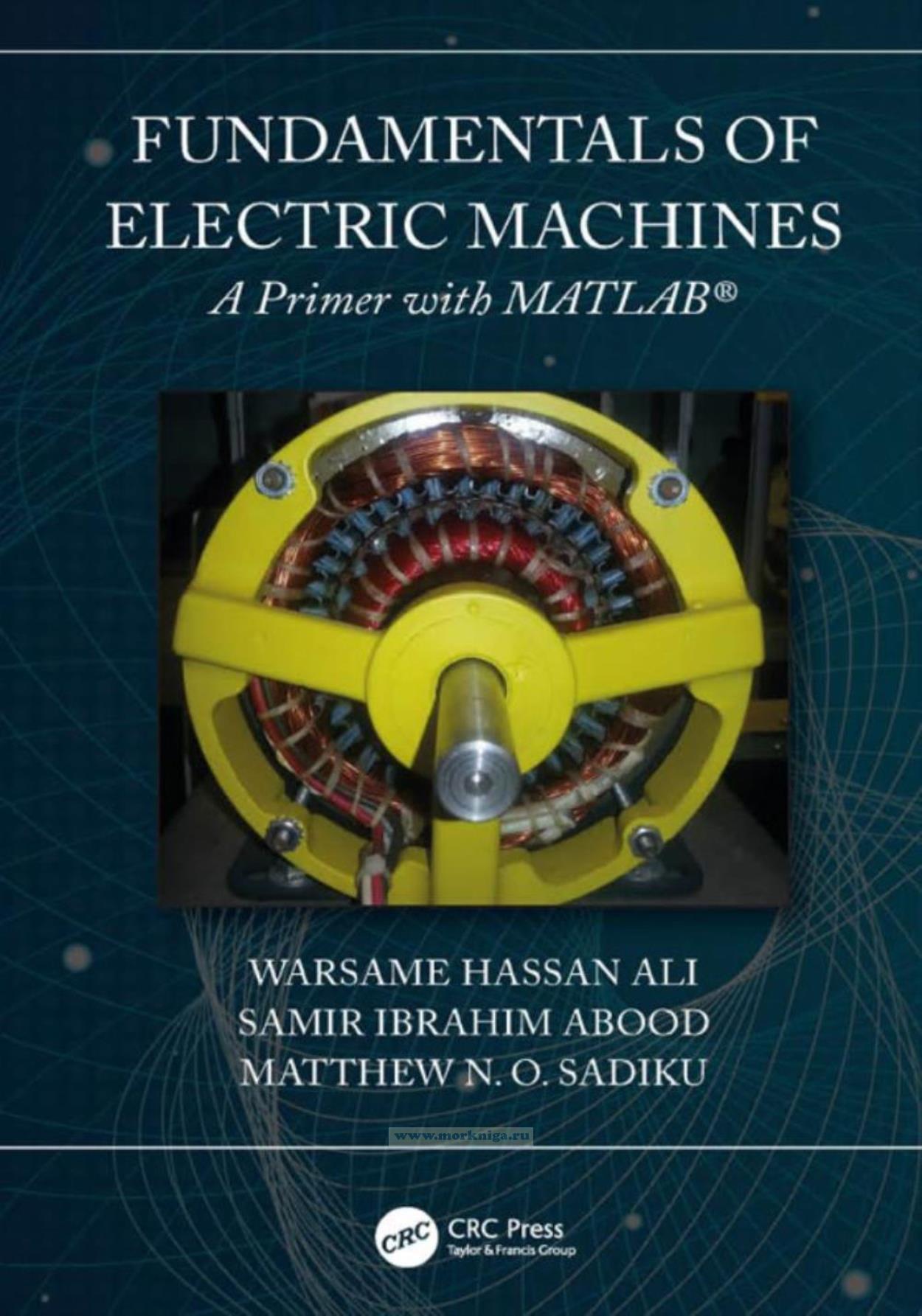
Fundamentals of Electric Machines/Основы электрических машин
Издание на английском языке
An electric machine is a device that converts mechanical energy into electrical energy or vice versa. It can take the form of an electric generator, electric motor, or transformer. Electric generators produce virtually all electric power we use all over the world.
Contents
Preface
Acknowledgments
Authors
1. Basic Concepts of Magnetism
1.1 History of Magnetism
1.2 The Cause of Magnetism
1.3 Types of Magnets
1.4 Applications of Magnet
1.5 Magnetic Materials
1.6 Lines of Magnetic Forces
1.7 Magnetic Force
1.8 The Direction of Magnetic Field Lines
1.9 Magnetic Field and Its Polarity
1.10 Magnetism of Magnetic Materials
1.11 Force Generated in the Field
1.12 Hysteresis Loop
Problems
2. Magnetic Circuit
2.1 Magnetic Quantities
2.1.1 Flux Density
2.1.2 Permeability
2.1.3 Magnetic Reluctance
2.2 Electromagnetic Induction
2.3 Induced Electric Motive Force (EMF)
2.4 Types of Inductance
2.4.1 Self-Inductance
2.4.2 Mutual Inductance
2.5 Stored Energy
Problems
3. Alternating Current Power
3.1 Sinusoidal Wave Cycle and Frequency
3.2 Electric Power Generation
3.3 Terms and Concepts
3.4 AC Current Values
3.4.1 The Maximum Value of the Alternating Current
3.4.2 Average Value of Alternating Current (Mean Value)
3.4.3 Actual AC Value
3.4.4 The Instantaneous Value of Alternating Current
3.5 AC Circuits
3.5.1 AC Circuit Containing Pure Resistance
3.5.2 AC Circuit with Inductive Reactance
3.5.3 AC Circuit with Capacitive Reactance
3.6 Series Impedance Connection to the AC Circuit
3.6.1 R-L Series Circuit
3.6.2 R-C Series Circuit
3.6.3 R-L-C Series Circuit
3.7 Parallel Connection
3.7.1 Parallel R-L Circuit
3.7.2 Parallel R-C Circuit
Problems
4. Transformers
4.1 Installation of the Transformer
4.2 Core Shape
4.3 Principle of Operation
4.4 Ideal Transformer
4.5 Transformer Rating
4.6 Transformer Operation
4.6.1 The Transformer Operation at No-Load
4.6.2 The Operation Transformer at Load
4.7 Non-ideal Transformer Equivalent Circuits
4.8 Determination of Equivalent Circuit Parameters
4.8.1 No-Load Test (Determine Rc and Xm)
4.8.2 Short-Circuit Test (Determine Req.H and Xeq.H)
4.9 Transformer Voltage Regulation
4.10 Three-Phase Transformers
4.10.1 Three-Phase Transformer Configuration
4.10.2 Three-Phase Transformer Connections
4.10.2.1 Three-Phase Transformer Star and Delta Configurations
4.10.2.2 Transformer Star and Delta Configurations
4.10.2.3 Transformer Winding Identification
4.10.2.4 Transformer Delta and Delta Connections
4.10.2.5 Transformer Star and Star Connections
4.10.3 Three-Phase Voltage and Current
4.10.3.1 Star-Delta Turns Ratio
4.10.3.2 Delta-Star Turns Ratio
4.10.4 Three-Phase Transformer Construction
Problems
5. Transformer Design
5.1 The Output Equations
5.1.1 Single-Phase Core Type Transformer
5.1.2 Single-Phase Shell Type Transformer
5.1.3 Three-Phase Shell Type Transformer
5.2 Choice of Magnetic Loading (Bm)
5.3 Choice of Electric Loading (?)
5.4 Core Construction
5.5 Electric Motive Force (EMF) per Turn
5.6 Estimation of Core X-Sectional Area Ai
5.7 Graphical Method to Calculate Dimensions of the Core
5.8 Estimation of Main Dimensions
5.9 Estimation of Core Loss and Core Loss Component of No-Load Current Ic
5.10 Estimation of Magnetizing Current of No-Load Current Im
5.11 Estimation of No-Load Current and Phasor Diagram
5.12 Estimation of Number of Turns on LV and HV Windings
5.13 Estimation of Sectional Area of Primary and Secondary Windings
5.14 Determination of R1, R2, and Copper Losses
5.15 Determination of Efficiency
5.16 Estimation of Leakage Reactance
5.17 Calculation of Voltage Regulation of Transformer
5.18 Transformer Tank Design
5.19 Calculation of Temperature Rise
5.20 Calculation Cooling Tubes Numbers
5.21 The Weight of Transformer
5.22 MATLAB Programs
5.22.1 Single-Phase Transformer Design Using MATLAB Program
5.22.2 Three-Phase Transformer Design Using MATLAB Program
5.22.3 Three-Phase Transformer Design Using MATLAB Program
Problems
6. Direct Current Machines
6.1 DC Machines
6.2 DC Machine Parts
6.2.1 Stator
6.2.2 Rotor
6.2.3 Commutator
6.2.4 Armature Coils
6.2.4.1 Lap Winding
6.2.4.2 Wave Winding
6.3 DC Generator
6.3.1 Calculate the Motive Force Generated by the Generator (E.M.F)
6.3.2 Method of Excitation of DC Machines
6.3.2.1 Separately Excited Generator
6.3.2.2 Self-Excited Generator
6.3.3 Losses in DC Generator
6.3.4 Efficiency Calculation
6.4 DC Motors
6.4.1 Types of DC Motors
6.4.1.1 Series Motor
6.4.1.2 Shunt Motor
6.4.1.3 Compound DC Motor
6.4.2 DC Motor Speed Control
6.4.2.1 Speed Control of the Shunt Motor
6.4.2.2 Speed Control of the Series Motor
6.4.3 Starting Methods
Problems
7. AC Motors
7.1 Single-Phase Motor
7.1.1 Induction Motors
7.1.1.1 Motor Construction
7.1.1.2 The Speed
7.1.1.3 The Theory of Work
7.1.1.4 Starting Methods of the Motor
7.1.2 Synchronous Motors
7.1.2.1 Synchronous Motor Construction
7.1.2.2 Synchronous Motor Operation Theory
7.1.2.3 Synchronous Motor Features
7.1.3 Universal Motor
7.1.3.1 Universal Motor Construction
7.1.4 Centrifuge Switches
7.2 Three-Phase Induction Motor
7.2.1 Construction of Induction Machines
7.2.1.1 Squirrel Cage Motor
7.2.1.2 Slip Ring Motors
7.2.2 Operation
7.2.3 Speed-Torque Characteristics of Induction Motor
7.2.4 Speed-Torque Characteristics of Induction Motors Using MATLAB Program
7.2.5 Basic Equations and Equivalent Circuit Diagram
7.2.6 No-Load Test and Blocked Rotor Test
7.2.6.1 No-Load Test
7.2.6.2 Blocked Rotor Test
Problems
8. Power Electronics
8.1 Rectifiers (AC-DC Converters)
8.1.1 Rectifier Types
8.1.2 Performance Parameters
8.1.3 Uncontrolled Rectifiers
8.1.3.1 Half-Wave Uncontrolled Rectifiers
8.1.3.2 Full-Wave Rectifiers
8.1.4 Rectifiers with Filter Circuits
8.1.5 Controlled Rectifiers
8.1.5.1 Thyristor Firing Circuits
8.1.5.2 The Use of a Thyristor in the Controlled Rectifier Circuits
8.1.5.3 Single-Phase Half-Wave Controlled Rectifier with Resistive Load
8.1.5.4 Single-Phase Half-Wave Control Rectifier with R-L Load
8.1.5.5 Single-Phase Full-Wave Control Rectifier with R-L Load
8.1.5.6 Single-Phase Full-Wave Half Control Rectifier with R-L Load
8.2 Power Electronics Circuits with MATLAB Program
8.2.1 MATLAB Simulation of Single-Phase Half-Wave Uncontrolled Rectifier
8.2.2 MATLAB Simulation of Single-Phase Half-Wave Controlled Rectifier
8.2.3 MATLAB Simulation of Single-Phase Half-Wave Controlled Rectifier with an Inductive Load
8.3 DC-DC Converter Basics
8.3.1 Step-Down (Buck) Converter
8.3.1.1 Transition between Continuous and Discontinuous
8.3.1.2 Voltage Ratio of Buck Converter (Discontinuous Mode)
8.3.2 Step-Up (Boost) Converter
8.3.3 Buck-Boost Converter
8.3.4 Converter Comparison
Problems
9. Concept of DC Drive
9.1 DC Motors Drive
9.1.1 Advantages
9.1.1.1 Easy to Understand the Design
9.1.1.2 Easy to Control the Speed
9.1.1.3 Easy to Control Torque
9.1.1.4 Simple, Cheap Drive Design
9.1.2 Disadvantages
9.2 Torque-Speed Characteristics
9.3 DC Motors Parametric Methods
9.3.1 Separate Excited and Shunt Motor
9.3.1.1 Adding Resistance to the Armature
9.3.1.2 Changing the Armature Supply Voltage
9.3.1.3 Changing the Field Flux
9.3.2 Series Motor
9.4 DC Drive Circuits
9.4.1 DC Drive Rectifier Circuits
9.4.1.1 Single-Phase Half-Wave Converter Drives a Separately Excited DC Motor
9.4.1.2 Single-Phase Full-Wave Converter Drives a Separately Excited DC Motor
9.5 DC Chopper Drive
9.6 Electrical Braking of Separate Excited DC Motor
9.6.1 Generator Braking
9.6.2 Supply Reversing Braking
9.6.3 Dynamic Braking
Problems
10. AC Drives
10.1 Advantages of AC Drives
10.2 Disadvantages of AC Drives
10.3 Speed Control of Three-Phase Induction Motor
10.4 Methods of Control Techniques
10.4.1 Speed Control of Three-Phase Induction Motors
10.4.1.1 Stator Voltage Control
10.4.1.2 Stator Frequency Control
10.4.1.3 Stator Voltage and Frequency Control
10.4.1.4 V/f Control Theory
10.4.1.5 Static Rotor-Resistance Control
10.4.1.6 Slip-Energy Recovery Control
Problems
11. Special Machines
11.1 Stepper Motors
11.1.1 Step Angle
11.1.2 How Stepper Motors Work
11.1.3 DC Motors versus Stepper Motors
11.1.4 Advantages of Stepper Motors
11.1.5 Disadvantages of Stepper Motors
11.1.6 Specification of Stepping Motor Characteristics
11.1.6.1 Static Characteristics
11.1.6.2 Dynamic Characteristics
11.1.7 Steady State Phasor Analysis
11.1.7.1 Phasor Expression of Variable Reluctance Stepping Motor
11.1.7.2 Phasor Expression of PM and Hybrid Stepping Motors
11.1.7.3 Equivalent Circuit in Frequency Domain
11.1.7.4 Pull-Out Torque Expression
11.1.8 Applications
11.2 Permanent-Magnet DC Motor
11.2.1 Construction
11.2.2 Working
11.2.3 Performance
11.2.4 Speed Control
11.2.5 Advantages
11.2.6 Disadvantages
11.2.7 Applications
11.3 Low-Inertia DC Motors
11.3.1 Shell-Type Low-Inertia DC Motor
11.3.2 Printed-Circuit (Disc) DC Motor
11.4 Servo Motors
11.4.1 Mathematical Model of Servo Motor
11.4.2 The Difference between Stepper Motors and Servos Motor
11.5 Brushed DC Motors
11.5.1 Stator
11.5.2 Rotor
11.5.3 Brushless Motor Basics
11.5.4 Advantage and Disadvantage of the Brushless DC Motor
Problems
Appendix A: Mathematical Formula
Appendix B: Complex Numbers
Appendix C: Introduction to MATLAB
Appendix D: Answer to Odd-Numbered Problems
Selected Bibliography
Index

