Сб с 10 до 16
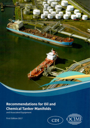
Recommendations for Oil and Chemical Tanker Manifolds and Associated Equipment. Рекомендации для коллекторов танкеров и химовозов и сопутствующего оборудования
Издание на английском языке
The present fourth edition of this OCIMF publication (first published in several decades ago, in 1971 and subsequently revised three times) in order to reflect the industry developments. This release edition does not contain any significant changes to the content of the document relating to the cargo/bunker manifolds as well as any associated equipment on board.
However, the authors of this volume have added a completely new Annex to the main body of the paper, willing to take into consideration the technical requirements that are there in a number of terminals and applicable to the tankers to transfer the cargo vapors to the shore-located facilities. We would also like to underline the fact that those recommendations have been provided with the sole intention to provide the required regulatory guidance to the operators of the vessels trading to the terminals where the installation of the vapor collection systems is mandatory.
The recommendations are supplementing the IMO-developed uniform safety design standards that are applicable to the shipboard marine vapor recovery systems as well as the USCG-issued regulations addressing the same matter. They shall only be treated as relating to the uniform manifold arrangements and shall not be considered applicable in any other cases.
Contents
Introduction
Glossary
Abbreviations
Bibliography
Note on metric/imperial conversion
Oil and chemical tanker tonnage categories
Section one
Manifold position
Centre of manifold
Distance from the ship’s side
Height of manifold
Spacing
Cargo vapour manifolds
Section two
Working platform and spill containment
Size and position
Spill containment draining
Strength of working platform
Loading arm jacks
Design of working platform
Access to working platform
Elevated working platforms
Section three
Manifold design
Carbon steel manifold
Stainless steel manifold
Assumptions for load calculations
Section four
Cargo and vapour manifold specification and fittings
Valves
Valve actuators
Distance pieces
Spool pieces and reducers
Blank flanges
Section five
Hose support at ship’s side
Curved plate or pipe hose support
Hose support position
Hose support strength
Section six
Bunker connections and other connections
Number of connections
Size of connections and reducers for oil bunkers
Size of connections and reducers for LNG bunkers
Strength
Location
Oil spill containment
LNG spill containment and protection
Other connections
Section seven
Lighting
Section eight
Lifting equipment
Safe working loads
Area of operation of lifting equipment
Operating criteria for lifting equipment
Personnel transfer by crane (man-riding)
Section nine
Deck fittings to facilitate hose handling at buoy moorings
Cruciform bollards
Bitts
Fairleads
Deck rings or lugs
Arrangements for ship to ship transfer
Section ten
Connectors for ship/shore emergency shutdown system
Section eleven
Standard manifold arrangements
Category ‘А, В, C’ Standard manifold arrangement, including vapour lines, for vessels up to 25,000 sdwt
Category ‘D’ Standard manifold arrangement, including vapour lines, for 25,001 to 60,000 sdwt vessels
Category ‘E & F’ Standard manifold arrangement, including vapour lines, for 60,001 to 160,000 sdwt vessels
Category ‘G’ Standard manifold arrangement, including vapour lines, for vessels over 160,000 sdwt
Typical manifold arrangement for a tiered chemical tanker


