Сб с 10 до 16
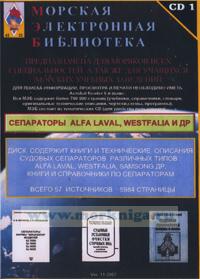
CD Морская электронная библиотека. CD 1. Сепараторы ALFA LAVAL, WESTFALIA и др.
Диск содержит книги и технические описания судовых сепараторов различных типов:
ALFA LAVAL
WESTFALIAи др. книги и справочники по сепараторам.
Всего 57 источников, 5984 страницы.
Морская электронная библиотека предназначена для моряков всех специальностей, а так же для учащихся морских учебных заведений
Содержание
Safety
1 Parameter Setting
2 Installation Parameters
3 Process Parameters
4 Factory Set Parameters
5 Sequence Diagram
5.1 Separation Sequence
System Description
1 Alarms
1.1 Alarm Functions
1.2 Reading Alarm History List
1.2.1 Alarm message explanation:
1.3 Alarm Reset
1.4 Abnormalities not displayed
2 Display Alarms and Actions
3 Alarm Tests
Operating Instructions
1 System Overview
1.1 Oil Flow
1.2 System Layout
1.3 System Components
2 The Process
2.1 Principle
2.2 Process Cycle Start
2.3 Discharge
2.4 Increased Water Content
Parameter List
1 Operating
1.1 Before Startup
1.2 Operators Panel
1.3 Startup
1.4 Manual Startup
1.5 During operation
1.6 Stop
1.7 Emergency Stop
1.8 After Emergency Stop
1.9 Cleaning In Place
1.10 Automatic Operation
1.11 Remote Operation
1.12 Emergency Operation
1.12.1 Manual Operation of the Separation System
Alarms and Fault Finding
1 Technical Data
1.1 Demand Specifications Water
1.2 Demand Specifications Air
1.3 System Data
2 Drawings
2.1 Flow Chart
2.2 Drawings
2.2.1 SA 850 Separator Mounting Drawing, DIN
2.2.2 SA 850 Separator Mounting Drawing, JIS
2.2.3 S 850 Separator Basic Size Drawing
2.2.4 S 850 Separator Foundation Drawing
2.2.5 Valve Block Oil, DN 40 Dimension Drawing
2.2.6 Valve Block Oil, DN 40 Assembly Drawing
2.2.7 Valve Block Water Assembly Drawing
2.2.8 Valve Block Air, Assembly Drawing
2.2.9 Control Unit EPC 50 Dimension Drawing
2.2.10 Starter Dimension Drawing
2.3 Electrical System Layout
2.4 Electrical Diagrams
2.4.1 Cable List
2.4.2 Interconnection Diagram, Starter
2.4.3 Interconnection Diagram, Starter, cont
2.4.4 Interconnection Diagram, Transmitters
2.4.5 Interconnection Diagram, Solenoid Valves
2.4.6 Interconnection Diagram, Solenoid Valves cont
2.4.7 Interconnection Diagram, Optiona Equipment
2.4.8 Circuit Diagram, Power Circuits
2.4.9 Circuit Diagram, Separator Starter and Feed Pump
2.4.10 Circuit Diagram, Remote Start Interlock (optional)
2.4.11 Circuit Diagram, ESD-relay and Trip Contacts (optional)
3 Remote Operation Systems
4 Specifications
4.1 Cables
4.2 Cable Routing
4.3 Oil, Water, Steam, and Condensate Piping
4.4 Ambient Temperature Limitation
4.5 Sludge Tank
4.6 Sludge Piping
5 Commissioning and Initial Start
5.1 Completion Check List
5.2 Initial Start-up
5.2.1 Calculating Operating Pressure
6 Shut-down and Storage
6.1 Shut-down after Use
6.2 Protection and Storage
6.3 Reassembly and Start up
Installation System Reference
1 Separator Design
1.1 Overview
1.2 The Drive Section
1.3 The Process Section
1.4 Sensors
1.5 Separating Function
1.5.1 The liquid balance in the bowl
1.5.2 Liquid flow
1.5.3 Discharge of sludge and water
1.5.4 ALCAP concept
2 Separator Service, Dismantling, Assembly
2.1 Technical Data
2.2 Connection List
2.3 Interface Description
2.3.1 Scope
2.3.2 References
2.3.3 Definitions
2.3.4 Goal
2.3.5 Description of separator modes
2.3.6 Remotestart
2.3.7 Handling of connection interfaces
2.3.8 Interconnection diagram
2.3.9 Electric motor
2.4 Nomogram paring tube
2.5 Periodic Maintenance
2.5.1 Maintenance intervals
2.5.2 Maintenance procedures
2.5.3 Tightening of screws
2.5.4 Service kits
2.5.5 Cleaning
2.6 Maintenance Log
2.7 Dismantling
2.7.1 Introduction
2.7.2 Tools
2.7.3 Frame hood
2.7.4 Bowl
2.7.5 Driving device
2.7.6 Centrifugal clutch
2.8 Actions Before Assembly
2.8.1 Cleaning
2.8.2 Inspection for corrosion
2.8.3 Inspection for cracks
2.8.4 Inspection for erosion
2.8.5 Exchange of frame feet
2.8.6 Lubrication of bowl parts
2.9 Assembly
2.9.1 Centrifugal clutch
2.9.2 Driving device
2.9.3 Bowl
2.9.4 Frame hood
2.9.5 Unbalance sensor (option)
2.10 Actions After Assembly
2.10.1 Control of machine plates and safety labels
2.11 Oil Change
2.11.1 Lubricating oil
2.11.2 Check oil level
2.11.3 Oil change procedure
2.11.4 Lubrication chart
2.11.5 Recommended lubricants
2.11.6 Lubricating oils
2.12 Lifting instructions
2.12.1 Lifting the separator
2.12.2 Lifting the bowl
3 Change of Circuit Board
3.1 Circuit Board Temperatures
4 Cleaning in Place
4.1 Cleaning in Place, Separator
Service Manual Spare
1 Separator S 850
1.1 Machine bottom part
1.2 Driving device vertical
1.3 Separator bowl
1.4 In- and outlet device
1.5 Belt driving device
1.6 Centrifugal clutch
1.7 Set of plates
1.8 Monitoring kit
1.9 Set of tools
1.10 Inspection kit
1.11 Overhaul kit
1.12 Lifting tool
2 Ancillary Equipment
2.1 Valve block water
2.2 Extra spare parts, valve block water
2.3 Valve block air
2.4 Extra spare parts, valve block air
2.5 Valve block oil
2.6 Water transducer
2.7 Spare parts kit, pneumatic change-over valve, water transducer
2.8 Connection kit, oil
2.9 Sludge outlet kit
2.10 Butterfly valve kit
2.11 Spare parts, EPC 50 Control Unit
2.12 Control unit
2.13 Remote operating system, desktop
2.14 Remote operating system, laptop
2.15 Remote operating system, profibus
2.16 Starter
2.17 Basic kit for starter
2.18 Sep. starter, 45-63A
2.19 Pump starter, 0,4-0,63A
2.20 Pump starter, 2.5-4A
2.21 Esd-relay kit
2.22 Trip contact kit
3 Index

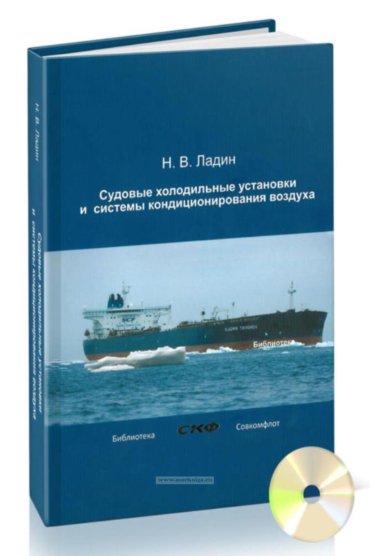
 Судовые холодильные установки и системы кондиционирования воздуха + CD
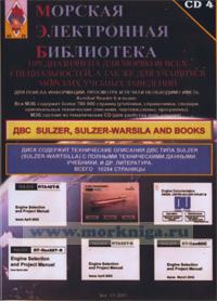
  CD Морская электронная библиотека. CD 4. ДВС SULZER, SULZER-WARSILA AND BOOKS
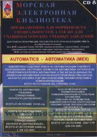
  CD Морская электронная библиотека. CD 8. AUTOMATICS - автоматика (мех)